


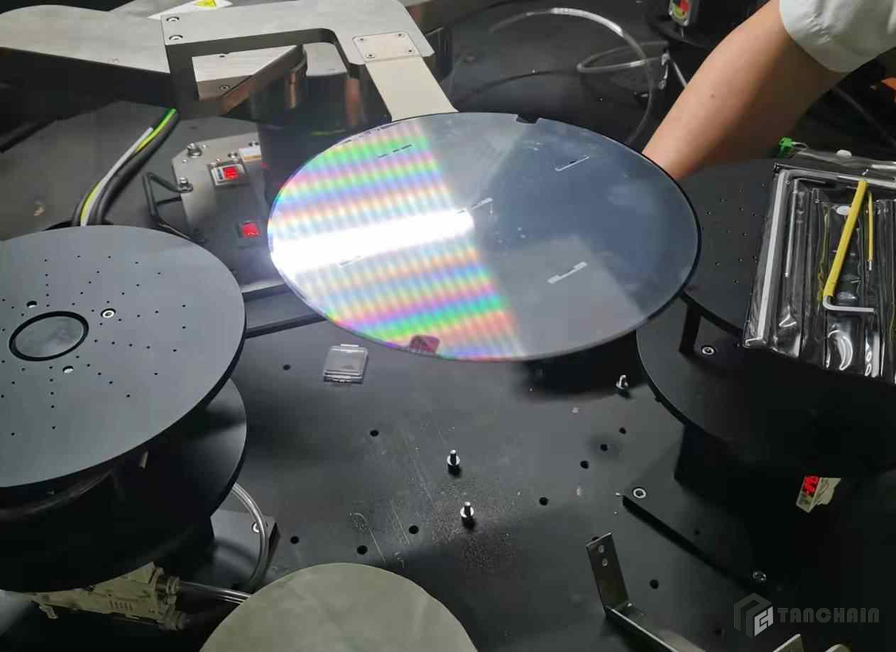
Carbon fiber in semiconductor manufacturing equipment is one of the most demanding material applications in modern industry, because the tools that make chips are judged by tolerances measured in nanometres. A lithography stage, a wafer handling robot, an ion implantation beamline or a metrology frame cannot tolerate the thermal drift, vibration or particle contamination that ordinary structural materials bring with them. Carbon fiber reinforced polymer (CFRP), combined with aramid and pre-oxidized fiber components, has become the quiet enabler behind the most precise machines on earth. This guide examines how carbon fiber semiconductor equipment works in practice — part by part, from the wafer stage to the cleanroom ceiling — and why high-performance fiber has become a standard engineering choice in fab tooling rather than an exotic one.
1. Why Semiconductor Equipment Sets the Hardest Material Requirements
Semiconductor fabrication is an industry defined by a paradox: it works at enormous scale and yet almost every critical dimension is tiny. A single wafer can contain tens of billions of transistors, and each patterning step must align to the previous layer within a fraction of a nanometre. Overlay, critical dimension, and yield all degrade the moment a machine's geometry changes, and geometry changes whenever a structure expands, vibrates, or loses stiffness.
That creates four material requirements that conventional metals struggle to meet simultaneously:
Dimensional stability: the tool must hold its shape across temperature swings, thermal cycling and long operating hours. The coefficient of thermal expansion (CTE) has to be close to zero, or at least matched to the metrology reference.
High specific stiffness: the structure must resist deflection and vibration without adding mass that would slow the stage, load the servo, or settle into low-frequency resonance.
Cleanliness: no outgassing, no shedding, no metallic wear debris that could become a particle defect on a wafer surface.
Vibration damping and control bandwidth: the machine must settle quickly after each move so that throughput and accuracy are not traded against each other.
CFRP answers all four. Its specific stiffness is several times that of steel or aluminium, its CTE can be engineered to near zero or matched to silicon, it does not corrode in the cleanroom chemical environment, and its internal damping kills the high-frequency ringing that would otherwise blur an exposure or a measurement.
2. Where Carbon Fiber Appears Inside a Fab Tool
Semiconductor equipment is a system of systems, and carbon fiber has moved into almost every subsystem where motion, thermal stability or structural economy matters.
2.1 Wafer Stages and Positioning Platforms
The wafer stage is the heart of any lithography or inspection tool. It accelerates at multiple g-forces, travels hundreds of millimetres in milliseconds, and must settle to nanometre precision afterwards. Every kilogram of stage mass has to be accelerated and then braked, so mass is directly converted into lost throughput and wasted energy. A carbon fiber stage structure, usually built from carbon fiber plate and bonded carbon fiber tubes with a matched CTE, gives the stiffness the control loop needs while cutting the moving mass. Because the composite can be designed so that its thermal expansion matches the interferometer reference frame, the stage's metrology does not drift as the tool warms up.
2.2 Gantry and Bridge Structures
Above the stage sits the gantry: a long beam that carries an optical head, an inspection sensor or a probe array across the full wafer width. It is a classic stiffness-to-weight problem. A carbon fiber gantry beam, often a large-section pultruded or roll-wrapped profile, raises the first natural frequency of the structure and pushes resonance away from the servo bandwidth. That single change lets engineers run the tool faster without exciting structural vibration, and it keeps the head-to-wafer distance stable across the whole scan.
2.3 Metrology Frames and Reference Structures
Metrology frames define the geometry that everything else is measured against, so their stability is the stability of the whole machine. CFRP frames are attractive because their expansion can be tuned toward zero, matching the low expansion of the silicon wafer itself. Where the frame must interface with glass scales, laser interferometers or capacitive sensors, matched-expansion carbon fiber plate keeps the readings honest as the tool heats and cools through a production shift.
2.4 Wafer Handling Robots and End Effectors
Wafer transfer robots move delicate, expensive wafers between process chambers at high speed, and their end effectors must be light, stiff, and impeccably clean. A carbon fiber end effector blade is stiff enough to hold a 300 mm wafer flat under acceleration, light enough to avoid sag and vibration, and free of the particle-generating wear that a machined metal blade can produce at its contact points. The same logic applies to lift pins, blade holders and transfer arms throughout the cluster tool.
2.5 Vacuum Chambers, Beamlines and Ion Implantation Hardware
Inside vacuum and beamline environments, carbon fiber and hybrid composite components reduce moving mass in proximity to delicate sensors and provide non-magnetic, dimensionally stable support structures. Ion implantation and electron-beam systems are sensitive to any magnetic or conductive structure that could disturb the beam, and to any thermal drift that could misalign apertures. Composite structures with carefully controlled fibre architecture allow these trade-offs to be managed without the weight penalty of a metal assembly.
3. The Materials and Their Specific Roles
No single fiber form solves a semiconductor equipment problem. The right answer is usually a combination, and understanding the roles is what separates a working design from an expensive one.
3.1 Carbon Fiber Plate for Precision Structures
Machined and quasi-isotropic carbon fiber plate is the go-to material for stages, brackets, spacer blocks and metrology members. Quasi-isotropic layups give predictable, in-plane stiffness with a low and controllable CTE, and the plate can be machined, drilled and bonded with the same tooling precision as aluminium — but without the thermal expansion and without the metallic contamination risk.
3.2 Carbon Fiber Tubes and Pultruded Profiles
Pultruded carbon fiber tubes and structural profiles provide long, constant-section members for gantries, robot arms and support rails. Pultrusion produces a certified, repeatable cross-section, which matters when a tool is built in series and every unit must behave identically. Tubes are also used for lightweight, rigid linkages and for the frames of automated material handling equipment inside the fab.
3.3 Carbon Fiber Prepreg and Fabric
Where the geometry is complex or one-off — a shaped shroud, a sensor housing, a contoured support — carbon fiber prepreg laid up over a mould gives the highest and most consistent fibre volume fraction and the tightest control of laminate architecture. Dry carbon fiber fabric with resin infusion offers a more economical route for larger, lower-volume parts. Both allow the laminate to be tuned locally, adding stiffness exactly where the load path demands it.
3.4 Aramid Fiber for Toughness and Insulation
Aramid fiber brings impact and abrasion resistance where composite parts meet handling equipment or human operators, and it is naturally electrically insulating and thermally stable. Aramid fabric and aramid filament are frequently used in hybrid laminates to protect the composite surface from chipping, and as isolating elements where electrical stand-off is required near sensitive electronics. Where a design needs a surface that resists impact without shedding conductive particles, an aramid-rich outer ply is a practical answer.
3.5 Pre-Oxidized Fiber for Thermal and Fire Protection
Semiconductor tools contain heaters, chucks and process chambers that reach high temperatures, and the surrounding structures need protection that is both thermally stable and electrically non-conductive. Pre-oxidized fiber (PANOX) felt, fabric and yarn provide flame-resistant, high-temperature insulation without the charring and degradation of common organic textiles. Pre-oxidized fiber components are used around heated chucks, in thermal barriers, and as fire protection for cabling and pneumatic lines inside the tool envelope.
4. Application Selection Matrix
The table below maps common semiconductor equipment duty points to the recommended fiber product form and the primary property it delivers. It is intended as a first-pass guide; final material selection should be confirmed against the actual load path, thermal budget and cleanliness specification.
| Equipment duty point | Recommended product form | Dominant property | Replaces traditional solution |
|---|---|---|---|
| Wafer stage structure | Carbon fiber plate, bonded tubes | High specific stiffness, near-zero CTE | Aluminium or steel stage body |
| Gantry / bridge beam | Pultruded carbon fiber tube, box profile | High natural frequency, low mass | Extruded aluminium beam |
| Metrology reference frame | Matched-CTE carbon fiber plate | Dimensional stability, low expansion | Invar or granite frame |
| Wafer handling end effector | Carbon fiber plate blade | Stiffness, lightness, cleanliness | Machined metal blade |
| Robot arm and linkage | Carbon fiber tube, pull-wound profile | Stiffness-to-weight, damping | Steel or aluminium arm |
| Sensor and optics housing | Carbon fiber prepreg layup | Shape freedom, thermal stability | Cast or machined metal housing |
| Contact and impact surfaces | Aramid hybrid laminate | Impact and abrasion resistance | Unprotected composite or metal |
| Heated chuck insulation | Pre-oxidized fiber felt and fabric | High-temperature, non-conductive insulation | Conventional organic textiles |
| Tool fire protection | Pre-oxidized fiber yarn and felt | Flame resistance, thermal stability | Mineral wool or glass blanket |
| Cleanroom handling furniture | Carbon fiber tube and plate | Low outgassing, low particle shedding | Painted steel frames |
The matrix is a starting point, not a substitute for engineering. Two duty points that look similar can require different fibre architectures once vibration mode shapes, thermal gradients and cleanliness class are taken into account.
5. The Engineering Case: Why Composite Beats Metal Here
Semiconductor equipment buyers rarely choose carbon fiber to save money on material. They choose it because the performance envelope of the machine cannot be reached any other way.
5.1 Thermal Stability That Keeps Overlay Honest
Overlay error is the single most expensive defect class in advanced lithography. A structure that grows by even a few micrometres over a temperature swing will shift the image it projects. By engineering the laminate so that CTE approaches zero, or matches the reticle or wafer reference, carbon fiber removes a whole error term from the budget rather than trying to correct it in software after the fact.
5.2 Stiffness and Damping for Throughput
Tool throughput is governed by how fast a stage can move and then settle. High specific stiffness lets the structure stay rigid at low mass, and the composite's inherent damping suppresses the residual vibration that would otherwise force a longer settling delay. The result is a machine that is both faster and more accurate, which is exactly the combination the industry pays for.
5.3 Cleanliness and Non-Magnetic Behaviour
Inside a cleanroom, a material that outgasses, corrodes or sheds particles is a liability regardless of its mechanical properties. CFRP with the right resin system and surface finish is inert, does not rust, and does not produce the metal wear debris that steel moving parts can generate. Its non-magnetic character is also essential near electron and ion beam columns, where a ferromagnetic structure would distort the beam.
5.4 Lifecycle Cost Across a Tool Generation
A fab tool is expected to run for many years, often across several process nodes, and downtime is measured in lost wafer starts. A structure that holds its geometry, does not corrode and does not need periodic re-calibration against thermal drift reduces the cost of ownership far beyond its purchase price. For a machine that can cost millions of dollars, the economics of stability are decisive.
6. Manufacturing and Quality Considerations
Composite parts for semiconductor equipment are held to tolerances and documentation standards that are far tighter than general industrial work, and the manufacturing route matters as much as the material.
Layup design: confirm the laminate is designed for the real load path and thermal gradient, not simply copied from the metal part it replaces.
CTE matching: verify the composite's expansion matches the reference structure or wafer across the full operating temperature band.
Resin and outgassing: select a resin system with low outgassing and validate it against the cleanroom and vacuum requirements.
Cleanliness and finish: specify edge sealing, surface treatment and particle control so the part does not become a defect source.
Metrology and traceability: require documented fibre content, layup schedule and dimensional inspection traceable to the delivered part.
Bonding and fastening: design joints to avoid galvanic coupling with metals and to keep bolt preload stable over thermal cycling.
Repairability: plan for bonded patch repair where feasible, so a minor damage event does not scrap an expensive assembly.
7. Trends Shaping the Next Tool Generation
Several forces are pushing carbon fiber deeper into semiconductor equipment. The first is the relentless shrink of process nodes, which tightens overlay and critical-dimension budgets every generation and makes thermal stability non-negotiable. The second is the rise of high-NA EUV lithography, whose larger optics and tighter tolerances place even greater demands on stage and frame stiffness. The third is the growth of advanced packaging and 3D integration, which multiplies wafer handling and inspection steps and therefore the demand for light, fast, clean handling hardware. Finally, the expansion of compound semiconductor and power device manufacturing brings new process temperatures and new chamber environments, expanding the role of pre-oxidized fiber and aramid insulation alongside carbon fiber structures. In every case the enabling theme is the same: a material that is stiff, light, dimensionally stable and clean.
Shanghai Tanchain New Material Technology supplies the complete fiber stack behind advanced equipment programmes — carbon fiber precursor and filament, carbon fiber staple, fabric, prepreg, plate, tube, pultruded profiles and finished composite parts, together with aramid filament, aramid fabric and the full pre-oxidized fiber range of filament, staple, yarn, felt and fabric. Whether the task is a prototype wafer stage, a metrology frame redesign or a production programme for handling hardware, our team can advise on the material form, fibre architecture and resin system that fit the duty cycle. Browse our carbon fiber product range or send an enquiry for a specification discussion on your next semiconductor equipment project.